R.A.A.D. Frame Design
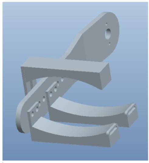
In order to aid patients suffering from SMA, a metallic frame to assist in the movement of the arm was developed. This frame is designed to be wheelchair compatible, and to move the arm using the chair as leverage. The frame is attached to the lateral side of the arm, and covers the length of the arm. Both sections of the frame, those attached to the upper arm and forearm, have sensor brackets to stimulate movement. Based on the research of previous assistive devices, the frame has been designed to be relatively small and unobtrusive.
Frame Design: Forearm
The forearm frame was mounted on the exterior of the upper arm section, farther from the patient, and curves inwards once separated. This inwards curve serves to make extension of the forearm more difficult after 135⁰. Drilled into the proximal end of the forearm brace is a ½” hole, and the length of the forearm has a pattern of holes spaced at ½” apart. The proximal hole is in place to affix the forearm to the upper arm. As can be seen in the image to the left, the holes are spaced so as to allow for the attachment of arm braces that will support the length of the patient’s arm at the proximal and mid-forearm. These braces will be cushioned to reduce any stress felt from prolonged use.
Frame Design: Sensor Placement
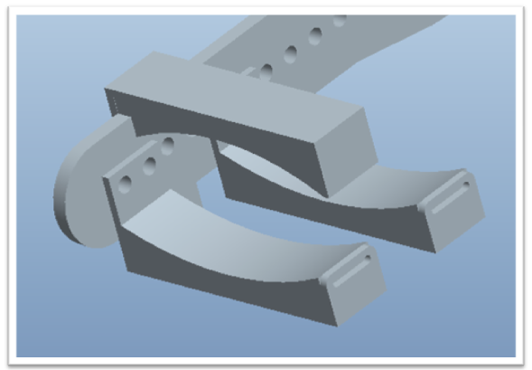
At the distal ends of both the upper arm and forearm sections of the frame, sensor brackets (shown in the figure to the left) were attached. These braces were used as the control mechanism for the arm. The interior of each cuff was lined with a cushion to prevent pain. Inside of the lining of the braces were pressure sensors. These sensed any force exerted on the brackets by the arm, and stimulated the motors in turn. The top bracket was built with a ½” slit running vertically down it in order to foster adjustability. Thus, a patient can get situated in the frame, have the bracket tightened, and then have it just as easily loosened to get out.
Frame Design: Upper Arm
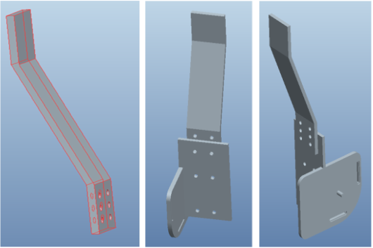
The upper arm has an axle extending from its distal end, which corresponds to the previously described ½” hole in the proximal end of the forearm. This gives the forearm rotational freedom while attached. The anterior of this section is rounded to accommodate this, but the posterior is flattened out, which will impede any further rotation due to contact with the inward curve featured on the forearm. Another aspect of the distal upper arm is the plate affixed to its posterior, attached to which is the motor for elbow flexion. It is between the frame and the motor plate that the sensor cuff for the upper arm will be located. It was given a 158⁰ curve in its shape, as the top superior end of the segment would originate behind the back of the chair. The slant would bring the segment forward to meet the arm of the patient, as seen to the left.. It shows a side, front, and back view of the segment that attaches to the upper arm. On the bottom are the various holes for adjustability.
Frame Design: Shoulder
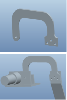
The proximal upper arm will be given a single range of motion which corresponds to flexion of the deltoid muscle in the lateral plane. The proximal section is attached to a bridge piece, which connects it to the back handles of the wheel chair in which the patient sits. The overall structure of the setup is visible in the figure to the left. The arch design was chosen due to the positioning the wheelchair necessitated; the handles of the wheelchair interfered with the swinging of the arm, so a wide arch prevented any clashing with the handles.
