Manufacturing and Assembly
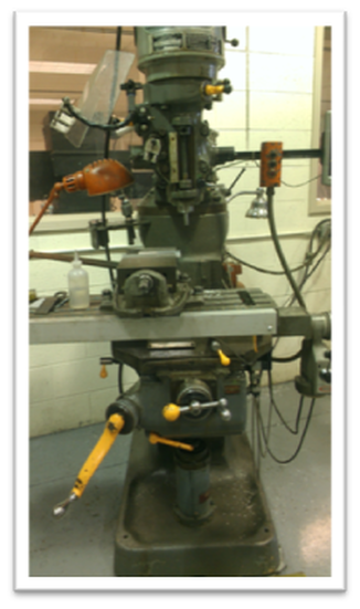
Once all of the designing work was completed, the manufacturing was started. The first part to be machined was the lower forearm plate.To manufacture the forearm plate that was now designed to be a straight piece of aluminum, a Bridgeport milling machine, shown left, was used to drill all of the holes needed for mounting. This was performed prior to cutting the shape of the part to allow the metal to sit in the mill more accurately due to have square edges on all sides. After drilling the holes, the shape of the part was cut using the band saw. A similar process was used in creating most of the plates that needed to be manufactured.
Motor Mount
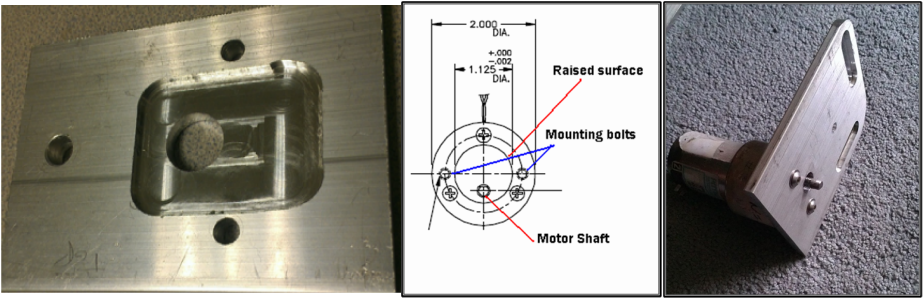
The motors both had a round lip that protruded 0.65” around the shaft. This was interfering while trying to mount the motor flush to its mounting location. To resolve this issue, a pocket was milled for this lip to sit into.
Gear Mounting and Elbow Assembly
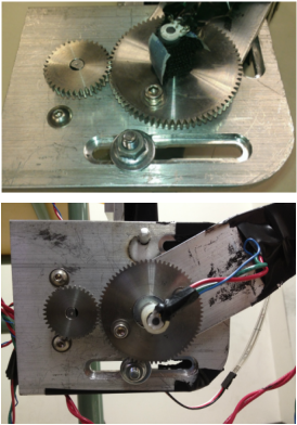
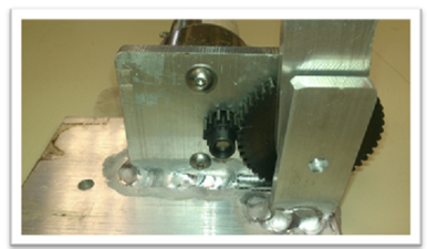
The gears for the shoulder plate and the forearm plate were attached to their corresponding locations by drilling and taping the plates. The gear affixed to the shoulder plate required counter sinking the mounting hole and a flat head screw to create a flush surface. Next step was to mount the forearm to the elbow plate. To do so the ¼” shaft needed to be welded to the elbow plate. Once welded, a sleeve bearing was pressed into the forearm piece to allow it to rotate freely on the shaft. A shaft collar was then added to lock the forearm onto the shaft.
After some initial testing, the weld on the backside of the elbow plate holding the shaft in place was starting to separate. The parts were disassembled and a new shaft was added that was ¼” longer to add a shaft collar in the backside of the elbow plate to add more strength to the joint. Another issue that had to be addressed with the elbow joint assembly was the location gear sitting on the motor shaft. The motor shaft needed to be machined in order to properly align the two gears.
After some initial testing, the weld on the backside of the elbow plate holding the shaft in place was starting to separate. The parts were disassembled and a new shaft was added that was ¼” longer to add a shaft collar in the backside of the elbow plate to add more strength to the joint. Another issue that had to be addressed with the elbow joint assembly was the location gear sitting on the motor shaft. The motor shaft needed to be machined in order to properly align the two gears.
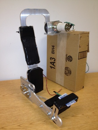
Shoulder Assembly
To assemble the shoulder, the motor and gearing were attached to the shoulder bracket as shown left. With the additional weight on this joint as compared to the elbow, this joint had supports on both ends of the shaft the shoulder rotates on. The shaft was held in place by shaft collars on both sides which allow the shaft to be removed if needed. The shoulder assembly was then bolted to the elbow assembly.
Assembled R.A.A.D